anti noise ATmega8 Circuit
Sering pas kita2 bikin project pake MCU (*baca:Microcontroller)
trus nge drive peralatan 380/220VAC macam motor, selenoid dll. Tuh MCU
ngadat kayak bajai… program HANG…kadang sama sekali gak mau jalan,
kadang reset sendiri program nya and then Temen2 langsung kompak bilang
“programnya tuh gannnn ndak beresss ….” dalam hati gua bilang: “Dammmnnn kenapa harus program(*baca:programmer) yang selalu jadi kambing hitam”. Tidak terima dengan perilaku diskriminatif ini
  , gua langsung browsing n ketemu ama document2 dari ATMEL Corp. doc910: Microcontroller in a Harsh Environment dan doc1619: EMC Design Considerations.
Setelah gua baca2, dalam mendesign sebuah circuit kita harus
memperhatikan EMC(electromagnetic compatibility) yang mencakup 2 hal:
, gua langsung browsing n ketemu ama document2 dari ATMEL Corp. doc910: Microcontroller in a Harsh Environment dan doc1619: EMC Design Considerations.
Setelah gua baca2, dalam mendesign sebuah circuit kita harus
memperhatikan EMC(electromagnetic compatibility) yang mencakup 2 hal:

 Gambar di atas menunjukkan cara penempatan decoupling capacitor.
Point penting juga untuk masalah grounding yaitu:

Gambar diatas menunjukkan penambahan induktor L yang berupa ferrite beads, sehingga terbentuk sebuah rangkaian filter. Spesifikasi L yang bisa digunakan adalah:

Karena sulit nyari ferrite beads yg sama persis kayak itu akhirnya gua ganti pake BLM31PG121
Rangkaian yang gua buat terdiri dari ATmega8, Port untuk LCD, MAX232, ULN2003 untuk driver relay, passive low pass filter untuk LM35. Penampakannya kayak gini:

Such an ugly design heughh!!! keliatan
ribet , mbulet coz gua musti bikin loop sekecil mungkin,, ndak boleh
asal connect jalurnya… saat uji coba gua pake relay 12volt yang biasa
di pake di panel2 listrik
keliatan
ribet , mbulet coz gua musti bikin loop sekecil mungkin,, ndak boleh
asal connect jalurnya… saat uji coba gua pake relay 12volt yang biasa
di pake di panel2 listrik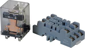 .
Bebannya gua ganti2 mulai dari kipas angin, setrika, blender, pokoknya
beban 220VAC yang ada dirumah. Setelah uji coba ternyata lumayan juga
ndak pernah Hang, setidaknya ada peningkatan, dulu gua gerakin kipas
220VAC yang kecill aja dah ngadat MCUnya…
.
Bebannya gua ganti2 mulai dari kipas angin, setrika, blender, pokoknya
beban 220VAC yang ada dirumah. Setelah uji coba ternyata lumayan juga
ndak pernah Hang, setidaknya ada peningkatan, dulu gua gerakin kipas
220VAC yang kecill aja dah ngadat MCUnya…
Advantage dari design ini:
• How the environment may affect the design (immunity).Affect from Environment dalam hal ini bisa diartikan noise yang dapat berasal dari RF frequency, switching powersupply dll. Bagian digital dari MCU juga sangat berpotensi membuat noise terhadap bagian analog MCU
• How the design may affect the environment (emission).


Current can only flow in loops. This is true for signals as well as for power supply current. Unfortunately, a current loop will emit noise, and the larger the loop, the larger the noise. Noise also increases with current and with frequency. A large loop is also more likely to receive noise. Loops should therefore be kept as small as possible. This means that every line that may emit or receive noise should have a return path to ground as close to the line as possible.Intinya: semakin besar sebuah Loop semakin rentan terhadap noise jadi buat grounding sedekat mungkin.
Point penting juga untuk masalah grounding yaitu:
Note that for a high frequency signal, the return path in a ground plane will be exactlyunder the track, even if this path is longer than the direct route. This is because the return path will always be the path of least impedance, and for a high-frequency signal, this is the path with the smallest loop, not the path that has lowest DC resistance.
For circuits that include both digital and analog circuits, the ground plane may be divided into an analog ground plane and a digital ground plane. This will reduce the interference between the analog and digital parts of the system.

Gambar diatas menunjukkan penambahan induktor L yang berupa ferrite beads, sehingga terbentuk sebuah rangkaian filter. Spesifikasi L yang bisa digunakan adalah:

Karena sulit nyari ferrite beads yg sama persis kayak itu akhirnya gua ganti pake BLM31PG121
Rangkaian yang gua buat terdiri dari ATmega8, Port untuk LCD, MAX232, ULN2003 untuk driver relay, passive low pass filter untuk LM35. Penampakannya kayak gini:

Such an ugly design heughh!!!
Advantage dari design ini:
- Relatif tahan noise
- LowPass filter 50Hz buat LM35 dengan mengatur nilai R multiturn menjadi 3100 – 3200 ohm. Hasilnya pergerakan nilai read ADC hanya 1-2bit. Lumayan oke lahh, kagak perlu utak atik program biar nilai LM35 nya stabil.
- Ada port buat LCD sekalian VR buat ngatur background contrast LCD
- ULN 2003 buat driver 3 relay
- MAX232 buat komunikasi serial RS232
- Pake 7808 jadi gak panas saat dikasih supply 12VDC
- Design terlalu gedhe buat chip sekelas ATmega8.
- double layer, lebih mahal n ribet bikin pcb nya
- Untuk PORT I/O belum dilengkapi VCC & Ground jadi kalo butuh musti ambil dari terminal power.
- Transistror power yang bisa digunakan footprintnya TIP31 kapasitas arus cuman 3A.
- Waktu trial cuman pake beban Home Appliance jadi belum bener2 terukur kemampuannya, buat agan2 yg mau coba pake beban yang lebih gedhe, monggo dipersilahkan tapi resiko ditanggung penumpang hehehehehehheee
- Belum dicoba di tempat dengan RF noise gedhe DOWNLOAD FILE PCB NYA KLIK DISINI
Tidak ada komentar:
Posting Komentar